The Power Stage. |
|||||
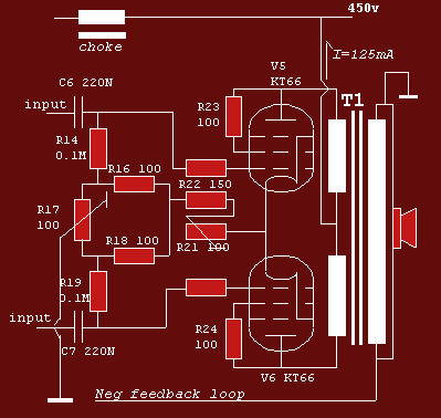
| T The drawing below reassembles the power stage. It works with better quality 6L6, 5881, El34 , KT66 and with the re-introduced KT77. It doesn't work with cheap phony imitations which are made by the same companies as the better ones that can often be recognized by their impressive vacuum envelopes. It has as little parts as possible. R21 regulates the dc current and R17 the dc balance. It is in important that all components connected between the grids 1 and the ground are first quality and checked thoroughly since malfunction draws to tube (s) past its limits. | |||||
 |
|||||
|
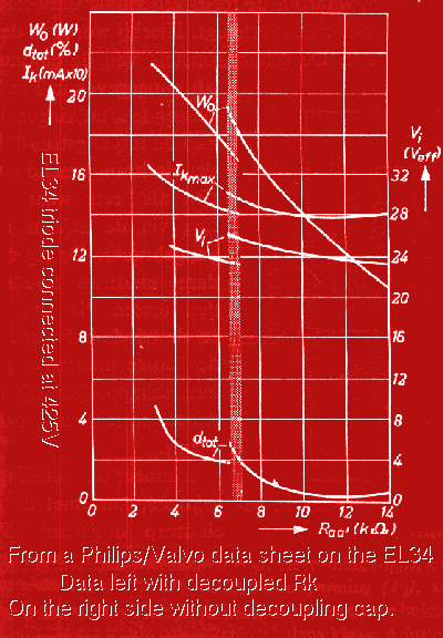
To measure the current through each tube, first check the dc resistance of each primary coils, then apply Ohm's law to calculate the tension needed over these coils for correct adjustment. For the resistors in the cathode circuit, take types that can handle 4 or 5 watts! The drawing below shows why a plate to plate impedance is your best choice. It also shows that if your speaker impedance is low, decoupling the cathode circuit with a capacitor of 100 mfd is a good idea at parties! These lines are drawn for a pair of EL34 but the constructor of those tubes made an effort making the tube interchangeable with the KT66 and friends. The resistance to the cathode must be chosen a bit lower, round 235 Ohms. For EL34 change R16 and R18 to 47 Ohms, R23 and R24 can also be decreased to 47 Ohms with the EL34 but that doesn't make that much difference. Leaving those resistors out however causes the tubes to oscillate at RF. KT77 and EL34 are interchangable. Note that the base connections of the EL34 have a separate connection for grid 3 where the KT66 and friends have a non connected (NC) connection. |
|||||
 |
|||||
|
The good thing about a decoupling capacitor that is not there is that you can't hear it! |
|||||
|
|||||