The Input Stage. |
|||||
 |
|||||
|
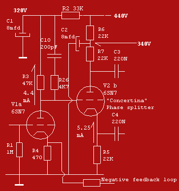
The input stage looks simple but was fairly new when presented by Williamson. The easy to obtain 12AU7 does the job just as good as the 6SN7 when the current is adjusted by a somewhat increased R4. The absence of an input capacitor means that the input signal must have no dc component. Check that. On many amps an suppresser resistor is connected between R1 and the grid of V1a to avoid instability (Typical value 10K) when however stability is not a problem such a suppresser should be avoided. R4 is not partially decoupled by a capacitor like in other amps and enjoys a lot of current feedback through R4 and as a result not much amplification (aprox.12X without the feedback loop) but very low distortion. On the plate side of the tube there is the direct connection to the grid of V1b which dictates the tensions and currents of the latter. C10 and R26 play an important role in controlling the supersonic characteristics and are discussed in the feedback loop section. V1b is connected as a cathodefollower because of the unusual high value of R5 it has full current feedback and therefore no amplification, no distortion and hardly any grid/plate capacitance. A cathode follower could better be called a grid follower since the cathode follows the grid as long there is any positive tension on the plate side. The voltage swing on the plate side of the tube is the mirror image of that gallant knight of the grid, the cathode since R5 and R7 are twins. That means as long as capacitance plays no role. The true fact is that the impedance on the cathode side of the phase splitter is only 1kOhms and on the plate side it is 22kOhms, which is still very low! Around 100k cycles ( depending on the grid/plate capacity of the following tube ) the output on the plate starts to drop. Unfortunately all phase-splitters have their disadvantages. Some engineers suggest that a 22K resistor on the cathode side is a good idea, fortunately the rest of the circuit can cope with the imperfections of the phase splitter in a very forgiving manner. At normal frequencies the phase splitter is, unlike many other circuits, very symmetrical. It is sometimes discussed that feeding the two tube systems in this stage from two HT sources is wrong and can cause low frequency oscillation. Feed them from one HT source is also wrong since the two systems are directly coupled and must therefore be allowed to adjust themselves to their own tensions and currents. Perhaps it is the best two allow the two tube systems to adjust themselves to 320v by adjusting R4 and R6 slightly and then, when voltages are identical, connect the hot sides of the two smoothing caps. Remember that altering R25 may alter all the tensions and currents in the circuit. |
|||||
|
|||||