The Unitran Project |
|||||
 |
|||||
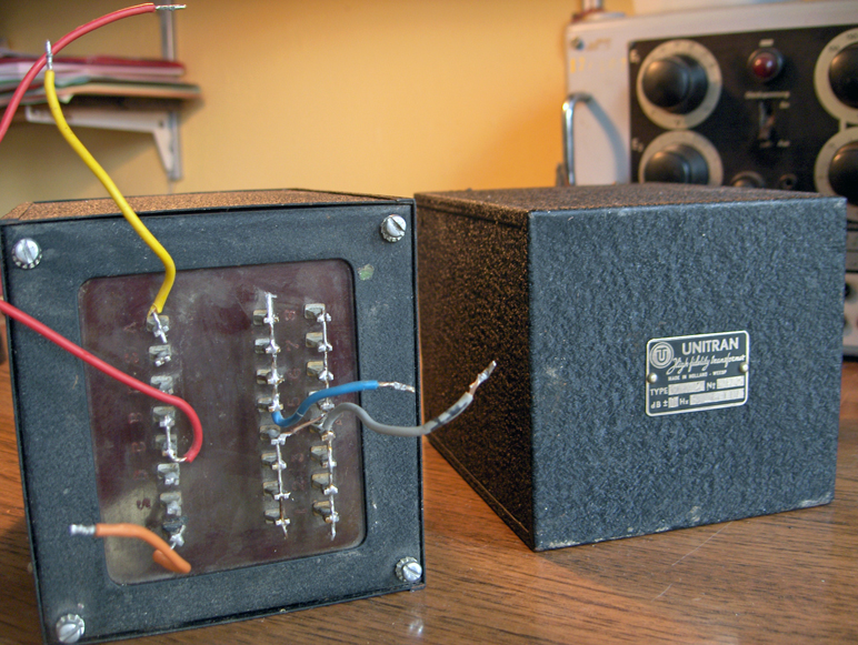
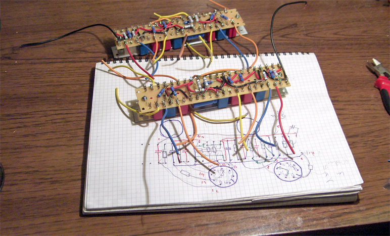
| The image above shows the two Unitran output transformers, type 10U72, that were made by the Dutch Unitran company in the early fifties. The author bought them second hand with the original documentation (the images at the bottom of this page) that led him to the Williamson design. | |||||
 |
|||||
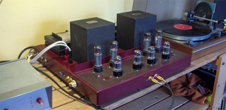
| Picture above. The amplifier with the Unitran transformers in action. On the right the Thorens TD record player and on the left the phono pre-amp. The main amplifier has a direct input on the front and a regulated input on the left side. The white knob is the volume control of the regulated input. The small blue push button on the left is connected to a small relay that switches between the direct and the regulated input. Also on the left side, towards the rear are two tumbler switches to switch the high tension of the power supply on and off. Further towards the wall is a mains switch. The top sheet of the chassis is made from 3mm (0.12") aluminium. 500 x 500 mm. (19x19"). The U shaped profile around the top sheet is also made from aluminium and measures 25 x 50x 25mm and is 4 mm thick. (1"x2"x 1" and 0.15" thick). The power tubes in this picture are the very old RSD branded EL34 (probably from the East German "Robotron" company) , the others are Electro-Harmonix 6SN7's.
The chassis carries two output transformers, two power transformers and two chokes and weighs approx. 25Kg or 55Lbs. |
|||||
 |
|||||
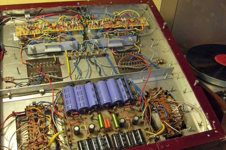
| Picture above, the bottom view of the amplifier with the Unitran output transformers. At the top the mounting boards of the passive components of the amplifier, below the profile on which the regulators and the power resistors of the power tubes are mounted, below that you see the bottoms of the output transformers and at the bottom, left and right the power transformers with component boards that carry the rectifiers for HT and the heaters, in the middle the pcb that carries the large 100 mfd electrolytic capacitors 6x and at the bottom the electrolytic capacitors for the power supply for the heaters. | |||||
 |
|||||
| Picture above. Designing the lay out of the component boards using the space below the boards for the capacitors. The red capacitors are the Wima MKP 220 Nf coupling capacitors. The blue capacitors bypass are also MKP and bridge the electrolytic capacitors for better sound. | |||||
 |
|||||
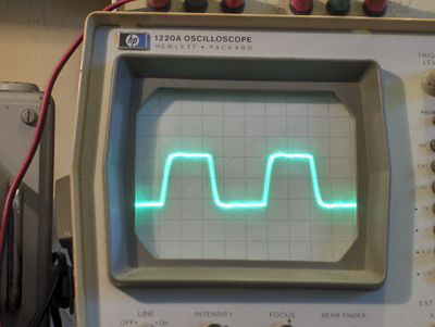
| Picture above, reproduction of a 10kHz square wave of the amplifier above while no negative feedback is applied. Instead of the loudspeakers an 8 Ohm dummy load is connected | |||||
 |
|||||
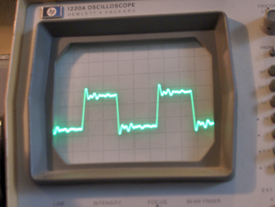
| Picture above, reproduction of a 10kHz square wave of the amplifier above with 20dB feedback and with C10 and R26 having values as prescribed by Williamson, The uniform waveform indicates the frequency on which the amp will oscillate when the feedback will be increased. Instead of the loudspeakers an 8 Ohm dummy load is connected. | |||||
 |
|||||
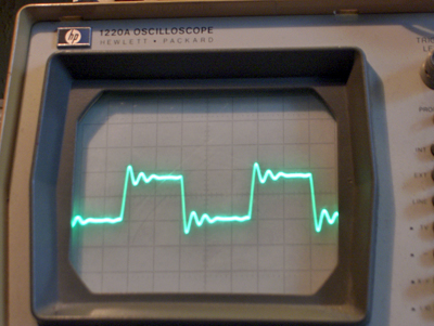
| Picture above, reproduction of a 10kHz square wave of the amplifier above with 20dB feedback and with C10 having a value of 220pF and R26 22k Ohm. The result seems fuzzier, introducing extra frequencies where a phase shift occurs results in more stability. This shows that it is a good idea to experiment with the values of C10, R26 since every output transformer is different even if it is said that it is made as Williamson prescribed. | |||||
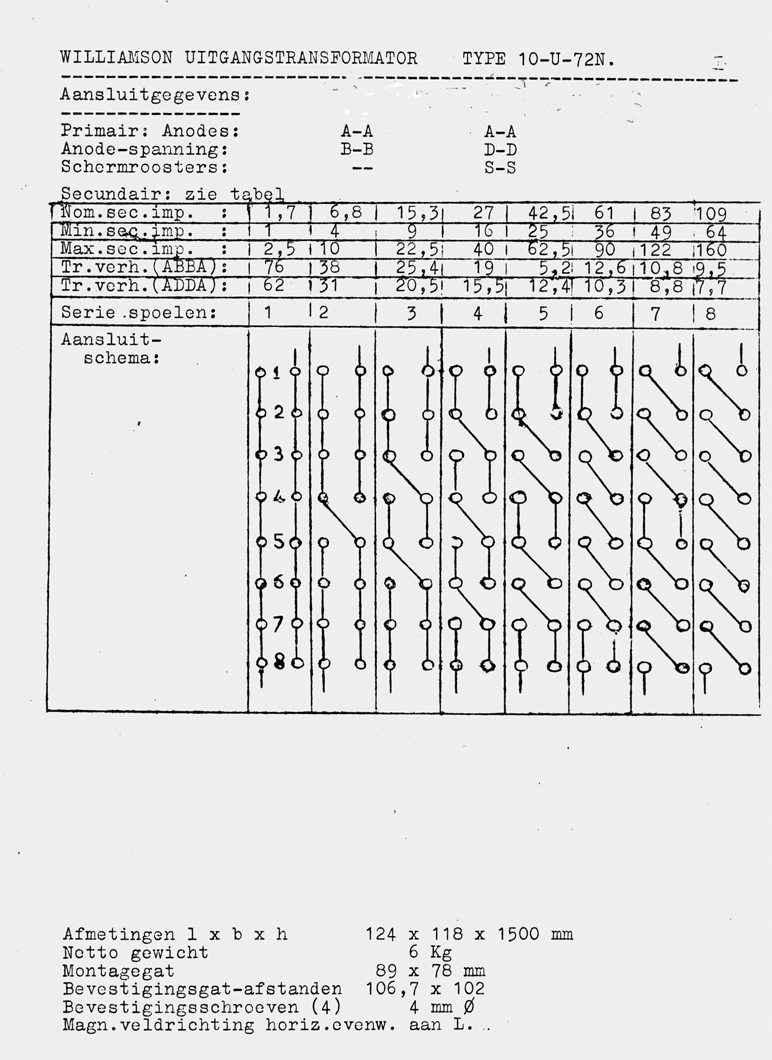
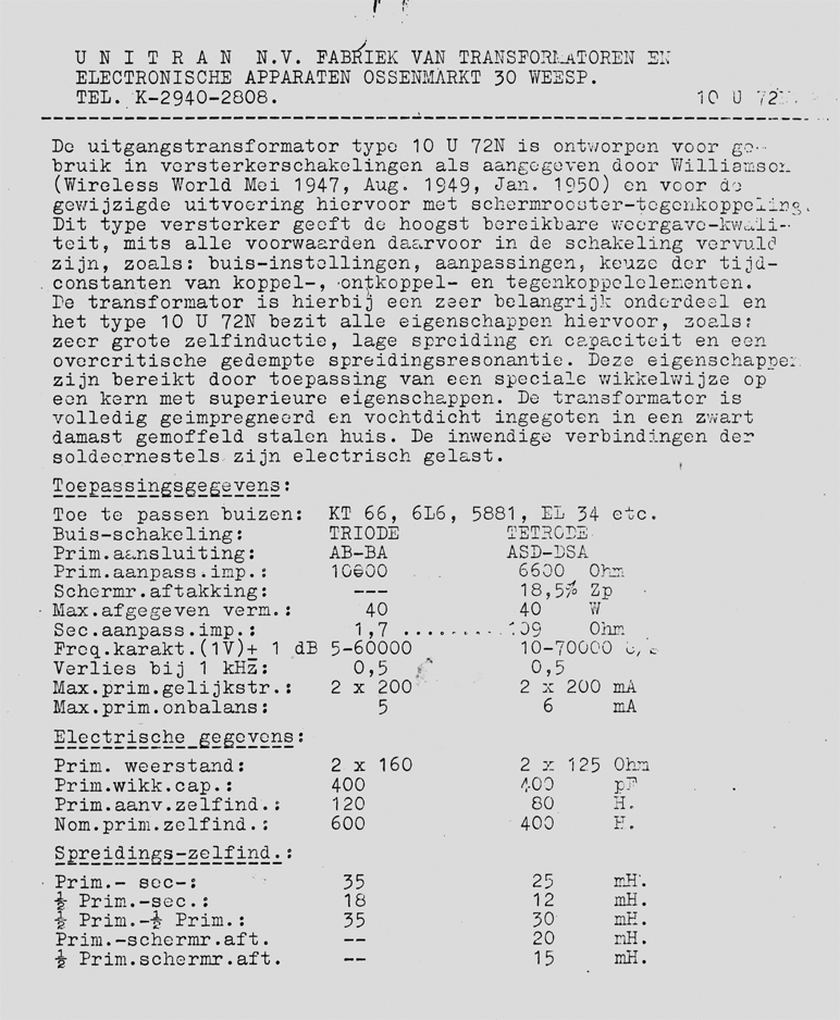
| The images below, the original documentation of the 10U72 Unitran output transformers from the early fifties. (note the 4 digit phone number). The document is in Dutch but the specs are obvious. | |||||
 |
|||||
|
The |
|||||
|
|||||