Applying Negative Feedback and Adjusting C10 and R26 |
|||||
| If your amp, without negative feedback and the C10/R26 circuit as described in the previous chapter, functions well and as it is a pleasure to listen to it, it is time to apply the negative feedback as it is an essential detail of the Williamson design. Essential before you apply the negative feedback is that the input sensitivity is determined. This is done by connecting the input to a signal generator with a sine wave signal of say 1000Hz and measure the output voltage over a dummy load.
For example: You put 100mV into the input and at the output you measure 6.00 Volt Now you connect a 25 kOhm or 50kOhm potentiometer adjusted to the maximum value in the place of R25 and look what happens to the output voltage. If the output voltage increases you have created a positive feedback. In that case you have to change the secondairy connections of the output transformer. If the output voltage decreases you have the desired negative feedback. Now you reduce the output voltage to one-third of the value you started with by decreasing the value of the potentiometer. The feedback is now 10dB. Switch the amp of, take the potentiometer out of the circuit and write the value down. it may be practical if you want to listen to a Williamson with 10dB negative feedback. After that you put the potentiometer into the circuit again and you reduce the output voltage to a value that is one-tenth of the value you started with. Now you reached a negative feedback of 20dB, the value Williamson preferred. Measure the resistance of the potentiometer and put a resistor of that value into the circuit. In most cases the value will be between 4k7 and 10k. Connect the loudspeakers and check with an oscilloscope if your amp doesn't oscillate and listen to some music. |
|||||
Adjusting C10 and R26 |
|||||
 |
|||||
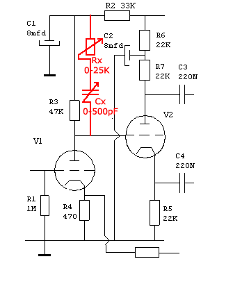
| The drawing above shows R26 and C10 in red as adjustable components. R26 and C10 were not present in the first Williamson diagrams. They were added when oscillation at high frequencies was noticed as widespread a problem. The right values of these components depend on a lot of circumstances like the tubes that are used and the exact electrical values of the output transformer.
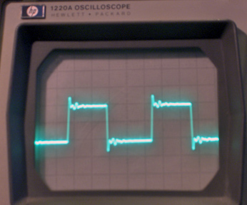
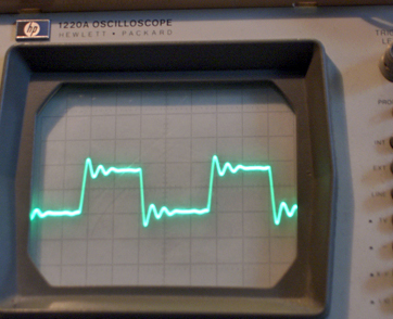
One can expect that values mentioned in the Williamson diagram were determined with the 6J5 tubes, the KT66 and the output transformer that was used to determine these values. The components do not add a special quality to the circuit but solve a problem by spreading out the frequencies where the phase shift may turn the negative feedback into positive feedback. In general this happens at frequencies around 100kHz.. In general the amplification factor of Williamson starts to increase from 80kHz on. When the output transformer and the electronic circuit with the tubes have the same frequency where phase shift reaches maximum oscillatiomnmay be inevitable. This effect can be boosted by the fact that the loudspeaker impedance goes towards infinite at frequencies around 100kHz. To determine the right values in your case (with your tubes and output transformer) you can take a course in theoretical physics and calculate forever or solder a potentiometer and a variable capacitor (from an old radio) provisionally into the circuit. connect a signal generator and an oscilloscope (with a dummy load) to your amplifier and turn the knobs of R26 and C10 while watching a square wave of 10kHz on your scope. Your goal is to avoid a large overshoot of the square wave and a clear recognizable sine wave form. Go for some fuzzy waves on top of the squares. Try to force the thing into oscillation, then you clearly see what you have to avoid. Once you reach the situation with little overshoot and some fuzzy waves on top of the square wave determine the values of the potentiometer and the variable capacitor and solder the components with these values in your circuit. With The Ultra Fine output transformers the best situation was when to whole R26 and C10 circuit was left out. See the image below on the right, there is not much to improve! With the Unitran output transformers the best result occurred with R26 was 22Kohm and C10 was 220pF. The image below on the right is with the values Williamson prescribed. If you count the waves on top of the squares you can predict that if oscillation occurs it will be at approximately 80 kHz. |
|||||
  |
|||||
|
|||||