Putting into Operation and Adjusting Bias |
|||||
| To switch on a newly build device for the first time is always stressful. Take time to check everything! | |||||
| If you want to put an newly build Williamson amplifier into operation, start without the negative feedback resistor (R25) and without the R26/C10 circuit. Your attention in this stage of your project should go into checking the plate voltages of the first stages of the amp and into checking the current through the power tubes. Start with R17 in the mid position and R22 to the maximum value and switch on for the first time. | |||||
 |
|||||
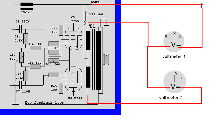
| The drawing above shows you the voltages to check. The values of R4 and R10 shown in this drawing are the values to be used with 6J5 tubes. If you use ECC82 (12AU7) or 6SN7 these values should be somewhat less then doubled to get the right bias for the V1-V4 tubes and to get the right voltages on the plates of V1-V4. If the voltages differ only 5% from the values shown, don't worry. | |||||
| Adjusting Bias of the Power Tubes | |||||
| One of the design typical design conditions of a Williamson amplifier is the shared cathode resistor of the power tubes. In the diagram above this resistor is composed out of R17, R16, R18, R 21 and R22. R17 and R21 are wire wound potentiometers. Added up to together with the potentiometers in the middle position the shared resistor should be around 300 ohm. The tubes communicate through this shared connection in a way that lowers the distortion in a significant way. If this resistor is bridged by an electrolytic capacitor the amplifier virtues and vices change in a way that it couldn't be called Williamson amplifier anymore. It is very important that the current through the tubes is equal because if it is not the core lamination of the output transformer will saturate magnetically which results in a lot of distortion and lack of bass reproduction. The smaller the air gap between the E's and I's off the core, the sooner the saturation takes place. With R21 the current through the tubes can be set and with R17, which regulates a small + voltage to the grids of the power tubes so that the flow of current through each of the tubes can be set . The current through the tubes X the voltage between cathode and plate should not exceed to the maximum dissipation of the tubes which in case of KT66, KT77. 807, 6CA5 and EL34 is around 25 watts. In most cases (depending on the HT voltage) this means that the current through each tube should be (and not exceed) 62mA. The difference between the currents through both tubes should be around 0. (zero). Therefore the tubes should be as equal as possible and should be bought as pairs. But even in an ideal situation this equality doesn't last forever! It remains an arranged marriage between the tubes. Since a real Williamson output transformer is wound in a symmetrical way (check that) the current though the tube can be determined by the voltage drop over each primary half of the output transformer. V : R = I. First thing you do is measure the dc resistance of each primary half of the output transformer when it is switched off to make shure that these values are equal. Next you connect 2 voltmeters as in the diagram below. Voltmeter 1 should be accurate and set to the 0 - 10 volt dc range. Voltmeter 2 should be able to return whether the difference between the voltage drop over both primary halves of the output transformer is positive or negative. Accuracy doesn't matter. Connect the input of the amplifier to the ground, connect a dummy load to the loudspeaker connection, adjust R17 to the middle of the range and R21 to the max. |
|||||
|
The |
|||||
 |
|||||
|
Image above shows how to connect voltmeter to the amp to set the bias of the power tubes
|
|||||
|
Now you turn on the amplifier and connect the voltmeters, adjust R17 for 0 volt on voltmeter 2 and R21 for a value way below the maximum value you have calculated for your situation and leave the amplifier on for an hour or so. Then with R21 increase the current slowly, step by step towards the calculated value, wait 15 minutes between each step and adjust the balance with R17 after every increase. If you think all values have finally met your calculations leave the amplifier on for a hour or so and then check one again.
That was only one channel Yes, it is a lot of work and when the tubes are still new you have to repeat it every week till they are "burned in". Then every half year or so,.. every year.. and towards the end of their live every now and then. Sometimes towards midlife tubes want to change partners. Sometimes one tube becomes lazy, the cathode emits less electrons then before, in that case the other tube may become overheated. The result of overheating is that the grid of the tube gets infected with the stuff on the cathode that emits electrons and the grid also starts to emit electron, becomes more positive, the tubes gets more overheated and an avalance takes place. The tubes are ready for adoption by the carbage man. Therefore a Williamson amplifier needs periodical maintenance which makes it unattractive as a consumer product, both for the industry and the consumer. |
|||||
 |
|||||
|
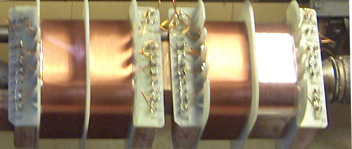
Image above, output transformer coils wound symmetrically and as a pair which results in an equal dc resistance of both halves of the primary.
|
|||||
|
If the dc resistance value of each primary half is not equal (not within say 3%) you should calculate the correct voltage drop over each coil and measure with identical voltmeters the drop over each coil and correct R17 and R21 till the calculated values for each primary half is reached. Build up the current slowly till it reaches the calculated value after a couple of hours.
|
|||||
| If all static values (the plate voltages and the currents through the tubes) are checked and OK your attention should go into checking the amplification factor of the amplifier, if this factor is also within the expected value, you should start listening to music though your new amp. Without negative feedback the sensitivity of the amp will be rather high, around 100 to 200 mV for full output, the amp will not sound very brilliant but distortion will be inaudible if the circuit is functioning correctly. and because of a damping factor between 20 to 30 there will already be some bass reproduction, depending on the kind of loudspeakers you use. If distortion is audible, something is wrong and you have to check the whole circuit. Expect the sensitivity of the whole circuit with 6SN7 tubes to be twice as high as with the ECC82 (12AU7) for full output.
Expect the maximum output to be around 12 Volt at 1000Hz when the turn ratio of your output transformer is around 35 and the dummy load you apply to the loudspeaker connection is 8 Ohm. |
|||||
|
|||||