The Circuit |
|||||
 |
|||||
| Above the circuit as it was published in the revised version in 1949., without the power supply. In tthe first version C10 and R26 were not present (in chapter 10 we will go into the C10 and R26 questions). The tubes used were V1-V4 6J5 V5 and V6 KT 66. In later versions the four 6J5' s were replaced by two 6SN7 's (double triodes). In those versions the values of R4 and R10 should be doubled for the right bias of the tubes. (check the plate tension). The tension from the power supply on the centre tap of the output tranformer should be around 445 volt. In chapter 9 we will go into the power supply design.
At the time this amplifier was designed electrolytic capacitors with values like 50 or 100 mfd were very expensive and rare. Chokes, on the contrary, were common and cheap. Nowadays it is the other way around. Choose for all electrolytical capacitors values like 50 or 100 mfd 450 volt operating tension (550 volt peak) and replace L1 in this diagram by a 1K resistor. bypass all electrolytic capacitors by high quality 220nf mkp capacitors (630volt) for better sound. The capacitors between the stages should be also be high quality 630volt mkp types. 220nf for the capacitors between the stages is big enough for the lowest notes. If you choose values like 1 mf low frequency oscillation may occur, at 0.5 Hz to1Hz (you won't hear it but may bring clipping closer). R25 connects the loudspeaker output to the input stage for negative feedback which reduces distortion, increases the frequency range, and decreases the input sensitivity to a value of 1 to 2 volt for full power output. Note that these values are ideal for digital equipment. The exact input sensitivity depends on the amount of negative feedback (Williamson prescribes 20 db (or 10 fold) but depends also on the amplification factor of the tubes that are used in this design. Determining the value of R25 will be discussed in chapter 10. |
|||||
The input stage |
|||||
 |
|||||
| The input stage looks simple but was fairly new when presented by Williamson. The easy to obtain 12AU7 (ECC82) and 6SN7 do the job just as good as the 6J5 when the plate current is adjusted by doubling the value of R4. The absence of an input capacitor means that the input signal must have no dc component. Check that. On many amps an suppresser resistor is connected between R1 and the grid of V1a to avoid instability (Typical value 10K) when however stability is not a problem such a suppresser should be avoided. R4 is not partially decoupled by a capacitor like in other amps and enjoys a lot of current feedback through R4 and as a result not much amplification (approx 10 to12X without the feedback loop) but very low distortion. On the plate side of the tube there is the direct connection to the grid of V2 which dictates the tensions and currents of the latter. C10 and R26 play an important role in controlling the supersonic characteristics and are discussed in chapter 10. V2 is connected as a cathode follower because of the unusual high value of R5 it has full current feedback and therefore no amplification, no distortion and hardly any grid/plate capacitance. A cathode follower could better be called a grid follower since the cathode follows the grid as long there is any positive tension on the plate side. The voltage swing on the plate side of the tube is the mirror image of that gallant knight of the grid, the cathode since R5 and R7 are twins. That means as long as capacitance plays no role. The true fact is that the impedance on the cathode side of the phase splitter is only 1kOhms and on the plate side it is 22kOhms, which is still very low! Around 100k cycles ( depending on the grid/plate capacity of the following tube ) the output on the plate starts to drop. |
|||||
The Driver stage |
|||||
 |
|||||
| The driver stage seems pretty uninteresting, though at a second glance, you may be tempted to think that decoupling R10 with a capacitor of say 100mfd is a good idea! Or maybe that cap is not there because of current feedback? Two times no! This peculiar construction is the backbone of the Williamson amplifier. There is no feedback through this resistor and amplification will not be significantly increased by decoupling it. In fact there is very little ac activity over this resistor and yet it decreases the distortion in this circuit enormously.
In the original Williamson two 6J5 tubes were used here, later versions used one 6SN7. 12AU7 (ECC82) may also be as well as the 12BH7. In all cases the value R10 should be increased till the plate tension reaches roughly 220V. In case of 12BH7 the values of R11 and R13 may be decreased to 39K because this tube likes a little higher plate current.. The amplification factor of this stage will be between 10 to 14 times depending on the tubes used. it is no coincidence that the driver stage uses the same trick with the common cathode resistor as the power stage. ( see the graph below) This construction has a very low distortion. It is also not accidental that the driver stage has a amplification factor that is about the same as the amplification factor of the power stage. The fact that both stages have an identical construction, both use triodes and have a more or less identical amplification factor means that they have a identical art of distortion. The distortion from the driver stage will be fed inversely into the power stage and the result will be almost no distortion. Lets call it "the Williamson Trick". The author has measured values of 0.05% THD at 10 watts over the whole amp without the negative feedback). |
|||||
 |
|||||
The Power stage |
|||||
 |
|||||
|
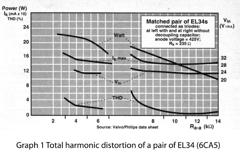
The drawing above shows the power stage. It works with 6CA5 or El34 , KT66 or 807 and with the re-introduced KT77.
The grapph above that shows the characteristics of the EL34 (6CA5 )is also applicable to the beam power types, KT66, KT77 or 807. The EL 34 was much later introduced then the KT66 and 807(by the Philips Valvo company) but was made interchangeable because the Philips Valvo company wanted a share of the market of the beam power tubes although it was a penthode it characteristics connected as a triode are similar R21 regulates the dc current and R17 the dc balance. In chapter 11 we will go deeper into this matter. It is in important that all components connected between the grids 1 and the ground are first quality and checked. thoroughly since malfunction draws to tube (s) past its limits. The resistors in the cathode circuit should be types that can handle 4 or 5 watts! To measure the current through each tube, first check the dc resistance of each primary coils, then apply Ohm's law to calculate the tension needed over these coils for correct adjustment. Very special is the complicated fat and heavy output transformer. The typical transformer made by the Williamson outlines weighs 6 Kg or 14 Lbs. In chapter 6 and 8 we will go deeper into the construction details of the output transformer. |
|||||
|
The |
|||||
|
|||||