The History |
|||||
| The Williamson Amplifier is named after its designer, the British inventor D. T.N. Williamson, who lived from 1903 till 1992 and worked in the electron tube industry in England at the time he designed the amplifier. The idea of designing a high quality amplifier was his own and was at first neglected by his employer , the Marconi Osram Valve Company , later the design reports of the amplifier were dumped by one of his directors at the desk of the editor of Wireless World, a major electronics magazine at that time. After the publication of the design in Wireless World in 1947 it were the readers of the magazine who picked up the design and overwhelmed the electronic part suppliers with a demand for parts to construct this amplifier. All over the world local constructors discovered the demand and started to produce the complicated output transformers for this amplifier and started to produce complete amps or do it yourself kits. All of them used the name “Williamson” to market their products. Generally it were good interpretations of the Williamson outlines with local characteristics. For example in the USA the 807 output tube was used, in the UK the KT66 and on the European continent the EL34 (6CA7) was favorite after it was introduced. One could say, the design became publicly owned , the Linux of that era, better than all the branded stuff. | |||||
 |
|||||
|
|
|||||
|
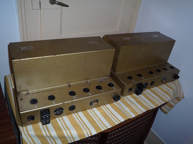
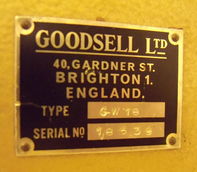
Picture above, a pair of Williamson mono-block amps without tubes produced by a British firm called Goodsell around 1952, pictures of this amp on this page by published with kind permission of Miguel de Mattos
|
|||||
|
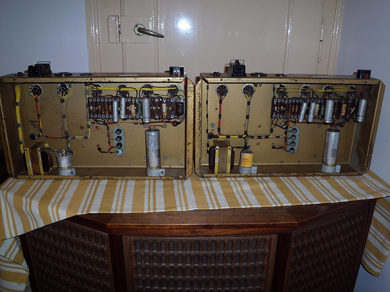
The diagram of this class A , push-pull triode amplifier at first sight is very simple, certainly if you compare it with a High End transistor amplifier. All passive components fit on a resistor mounting board as you can see in the picture of the bottom of the Goodsell. The circuit consists out of three stages coupled with two pairs of coupling capacitors and an overall negative feedback over all these stages and the output transformer. This means that phase shift in the higher or lower frequencies can cause oscillation therefore the output transformer must cover a very wide frequency range and has to be very carefully designed. 10 to 60.000 cycles band width within 2 dB, 15 Watts at 0.1% THD appealed to everyone’s imagination. Only the USA made and priceless McIntosh amplifiers might reach this performance. Although there were hardly any sound carriers that needed this kind of performance tens of thousands of these amps were made worldwide.
|
|||||
 |
|||||
|
Picture above bottom view of a pair of Goodsell Williamson amps.
|
|||||
|
David Hafler an Herbert Keroes published an article on the Ultra Linear Operation of the Williamson Amplifier in Audio Engineering in june 1952. It promised far more output power at slightly higher distortion and a little less damping factor. The consumer only needed to replace the very expensive output transformer for a transformer with a somewhat lower Z a-a and taps on the primary to connect to the screen grids. This altered the push-pull operation of the tubes from triode to pentode with negative feedback over the screen grid. The operation was called Ultra Linear, the concept was patented by the British inventor Alan Blumlein in 1937. On paper this seemed a deal no one could resist, power was hot, who needed a 15 Watt amp if you could have a 30 Watt amp at the same price?
A flaw of the original Williamson was class A operation with bias that had to be adjusted periodically because of the unequal wear of the tubes. The industry doesn’t like consumer goods that have to be serviced. OK, you can drive your car to the dealer but carrying your amplifier to the shop..? The industry standard for audio amplifiers became class A-B self-biasing amps with a strong feedback to reduce the distortion that where later replaced later by transistor stereo shoebox amps with simple controls that could be operated by anyone. The Williamson was a hobby thing of the wealthy from the early fifties and the general public had never heard how it sounded. In the sixties all remaining equipment that looked technical was banned from the living quarters and moved to the attics. |
|||||
 |
|||||
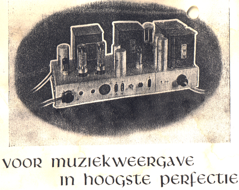
| The scan below show the headline of an article published in august of 1952 Radio Bulletin, a Dutch DIY magazine on radio electronics. It says "for music reproduction in the highest perfection". The article was published in a lot of associated magazines on the European main land and introduced a version of the Williamson with parts that were availlable on the continent. | |||||
 |
|||||
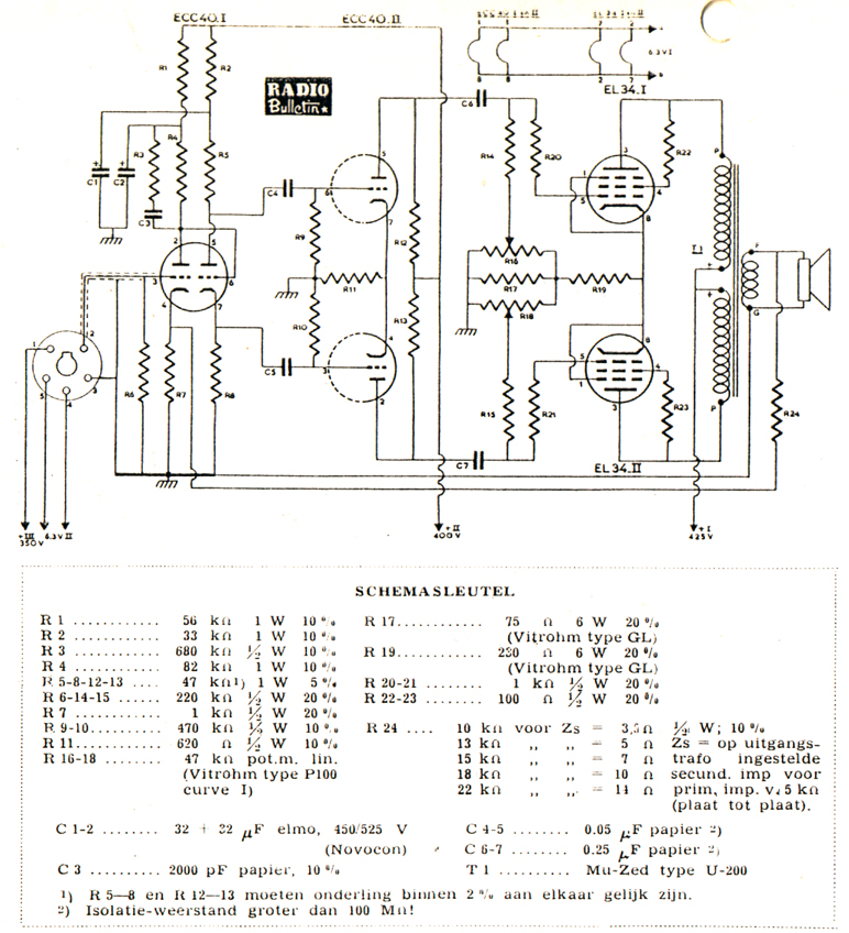
| The scan below shows the diagram of the European mainland version of the Williamson that is mentioned above. The tube used in the first three stages is a double triode called ECC40, a rimlock type tube with eight pins which is out of production. The final stage uses EL34's (6CA7). The circuit for adjusting the bias of the EL34's with low power potentiometers R16 and R18 is a bit tricky. Designed obsoletion one would say now. One year later the UltraLinear version of this amplifier was introduced. The language used in the diagram is Dutch. | |||||
 |
|||||
|
|||||