The Ultra Fine Output Transformer Project. |
|||||
 |
|||||
| Picture above shows a pair of home grown output transformers for a Williamson amplifier. The author likes to call them "The Ultra Fine". Investing time in making tube amplifiers without the certainy of the quality and availability of the output transformers is in the opinion of the author not very tempting. The output transformer has a place in the centre of the diagram of the amplifier, between the loudspeaker and, through the feedback, to the input. All values and qualities of the comcept depend on the output transformer. Luckyly a lot is known about the original design, Williamson descriped it thoroughly. | |||||
 |
|||||
| Drawing above the lay out of the output transformer Williamson proposed. Its core was equal to the DIN E-I 150 that is used nowadays. The core is 150mm High (6'') and with the copper weighted 6kg. (13lbs). The core material was at that time a premium quality but to modern standards it is only standard grade. The reason Williamson used such a core was that he wanted to reach an initial inductance of 100H and a max. inductance of 600H. This can only be reached with a enormous core and 4400 turns with a standard grade core. To keep the leakage inductance within acceptable margins the primary is divided in two mirror-identical sections that are each divided in 5 sections of 4 layers of 88 turns of 0.3mm copper. In between those 5 primary sections are 4 secondary sections consisting of 2 layers of 44 turns of 1.2mm. ( 1''=25mm). All layers are insulated with 0.05mm paper and all sections are interleaved with 0.4mm insulating linen tape. The drawing gives an impression of how things are connected. All primary coils are in series and the secondary can be connected in series and parallel thus giving the loudspeaker impedance's of 1.7, 6.8 and 15.2 Ohms. This transformer works! For those who want to try themselves to make such a transformer the author found out that it is not entirely impossible with a winding machine. The most important feature of such a machine is a reliable mechanical counter. The transformer, although it is very good is somewhat out of time. The dimensions are not very practical, the copper losses in the primary are with 320 Ohms between the plates somewhat high and a leakage induction with 30mH is also somewhat high and last but not least, the output impedance's are impractical. The first thing you must know about output transformers is that the square root of the impedance ratio is the turn ratio. The second thing, leakage inductance can easily be measured with a LCR meter. Short the secondary and measure the inductance that is left over in the primary. Don't be surprised when it is much lower as 30mH. The author reached values as low as 3.8 mH. The selfinductance of the entire transformer is not so easy to measure since it depends on the excitation of the iron core. Most LCR-meters don' t like the variable values of the cores that exceed 100H. Therefore it is more practical to calculate the inductance the following way: First determine the impedance of the entire primary coil by measuring the current through the primary with an Am-meter in series connected to a AC source of say 4 to 25 Volts. Expect values between 75000 Ohm and 250000 Ohm. Then devide the value of the impedace by ( 2.pi times the frequency of your AC source) Depending on the AC tensions the result for the UltraFine transformers was 250H at 5 volt and 500H at 25 volt. Since the quality of core material has improved enormously over the years it is not impossible to use a smaller core of grain oriented material with somewhat less turns and still reach a higher primary inductance. Although it is possible to calculate everything of a transformer it is hard to say how a transformer performs once it is wound. The best guaranty that a do it yourself transformer works is sticking to the original Williamson design and diminish the diameter so that you reach a turn ratio of 35 when the entire secondary is connected in two parallel sections that are put in series. The author has after years finally developed a transformer that is better then the original Williamson on a E-I 130B core of grain oriented material. It has sectional windings, has a leakage inductance of 8mH, 150 Ohms dc between the plates, 0.12 Ohm dc secondary and has a secondary impedance of 8 Ohms to a primary of 10600 Ohms. The inductance varies from 250H at 4 volts to 500H at 25 volts. Its still weighs 5.2 Kg (9lbs). The winding details are shown below. Since the author has changed his pair of KEF Chorales for a pair of B&W DM4's the listening results of amps with yhe UltraFine output transformers are stunning. Even with the most complicated music every instrument has a place and listening means dancing! |
|||||
 |
|||||
| Drawing above, the layout of the Ultra Fine output transformer as designed by the author. It has on each side of the primary 4 coils of 4 layers and 3 coils of 2 layers, interleaved by 6 secundary coils of 2 layers. Each layer in every coil separated by the right amount of polyester foil. Every coil is separated by a number of layers of polyester foil.
Great advantage of this transformer is that it doens't need the C10 and R26 circuit at all to remain stable. The bass notes are just a though dryer and darker then that of the original Williamson, probably because of the lower copper losses. The author still has a few examples of these transformers in stock. If you are interested you can visit and listen before you buy. Prices are 500 euro's a pair. For information on this subject please mail ideas@xs4all.nl mentioning OPT as subject. |
|||||
 |
|||||
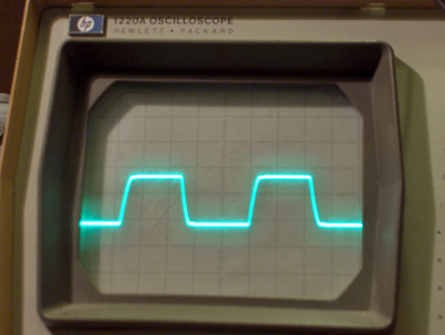
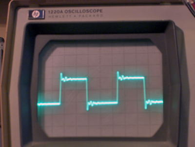
| Picture above, the 10kHz square wave reproduction of an Ultra Fine transformer with no negative feedback applied. Note that the rise time is well below 5 microeconds. | |||||
 |
|||||
| Picture above, the 10kHz square wave reproduction of an Ultra Fine transformer with 20dB negative feedback applied without the C10, R26 circuit. Tubes used are ECC82 (2X) and EL34 (2X) | |||||
 |
|||||
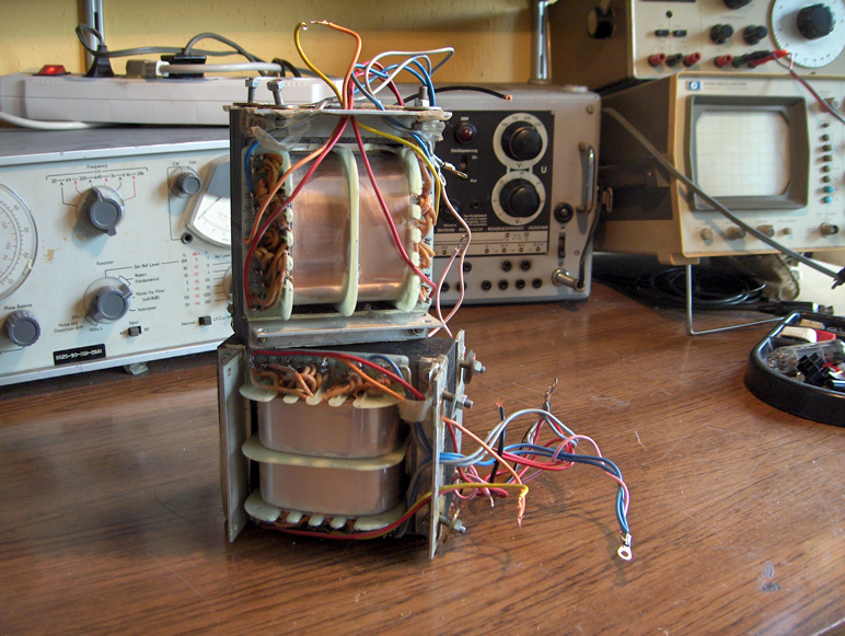
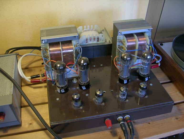
| The Ultra Fine output transformers on their test station without magnetical shielding. Please note that it is very dangerous to have an amplifier like this where the HT connections on the transformer can be toughed! | |||||
 |
|||||
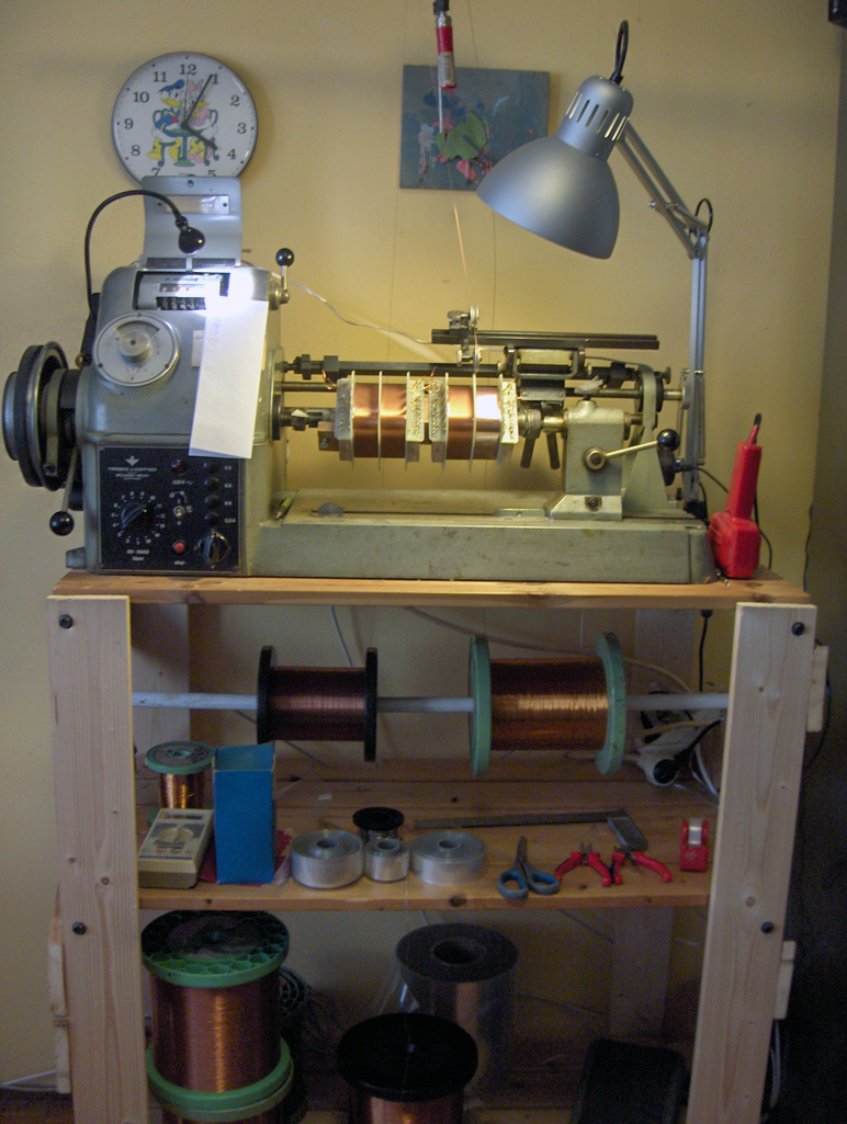
| Picture above, the authors winding station making a pair of coils for the Ultra Fine output transformers. The machine is a German made Frieseke & Höpfner made in the fyfties. | |||||
|
The |
|||||
|
|||||