Power Supply and HT Time Delay |
|||||
 |
|||||
| The diagram above on the right side of the drawing, printed fat, shows the power supply as used by the author. In the original Williamson amplifiers, as in all amplifiers before the sixties of last century, rectifier tubes were used. The most simple circuit has a power transformer with a secondairy section for 315 volt (which results after rectifying in a HT of 440 volt) and a secondairy section of about 10.5 or 7.5 volt which results after rectifying in approximately 12.6 or 6.3 volt. (depending on whether you want to put pairs of heater is series or not). If the AC from the transformer is too high or too low to reach 6.3 or 12.6 volt DC, add one or two turns to the transformer.
For a single channel amplifier the transformer must be capable of delivering 100 watts of power. In the diagram above R50 and R51 are applied to lift the tension of the heaters to approximately +50 volts compared to the ground. This is done because the cathode of V2 in operation has +100 volt compared to the ground and a difference of 100 volt between the heater and the cathode would be close to the limit of the specification. R50 and R51 also discharge the HT electrolytic capacitors when the power is switched of. Sw2 is used to switch the HT on by hand when the cathodes have reached their operating temperature after a minute or so or to put the amplifier in stand-bye. |
|||||
 |
|||||
| The image above shows how an automatic high tension time delay can be realized when the power transformer has an extra section for a pre-amplifier. | |||||
 |
|||||
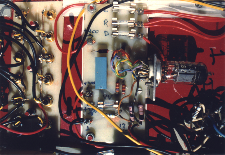
| The picture above shows the simple time delay circuit. The blue square thing is the relay. The whole thing is fitted at the bottom of an amplifier doing its job secretly and in silence for 20 years. | |||||
|
The |
|||||
|
|||||